Assemble Your Own All-in-One PC with GIGABYTE Thin Mini-ITX Motherboards
All-in-One PCs are becoming a very popular choice
for many of today’s consumers, offering an integrated and slick PC
experience that also saves space. The new Thin Mini-ITX standard from
Intel® introduces a set of guidelines that not only help to
nurture vendors and manufacturers, but also provides DIY users the
opportunity to build their own All-in-One PCs.
The new Thin Mini-ITX standard outlines several
key guidelines concerning the design and integration of the key
components that make up an All-in-One PC, most notably the position of
the motherboard in relation to the chassis. GIGABYTE currently has
several Thin-Mini-ITX motherboard models that comply with these
guidelines including the latest GIGABYTE 8 series Thin Mini-ITX
motherboards, supporting 4th generation Intel® Core™ processors with onboard Intel® HD Graphics.
|
| |
Kluczowe komponenty |
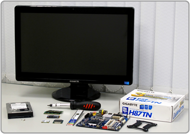
Here is a list of the components that we used to construct our All-in-One PC.
|
-
1 GIGABYTE H87TN Motherboard
-
1 4th generation Intel® Core™ Processor
-
1 Kingston mSATA SSD
-
2 x 2GB Transcend SO-DIMM DDR3 Memory Modules
-
1 Atheros AR5B22 Mini PCI-E wireless network card (802.11a/b/g/n and Bluetooth 4.0)
-
1 Thin Mini-ITX-compliant chassis with integrated LED touch screen display
Note: The CPU heatsink and fan are supplied with the chassis and are specific to that chassis
design. Some chassis manufacturers may specify certain limitations regarding CPU model compatibility due to thermal design constraints. |
|
| |
|
|
| |
Installation |
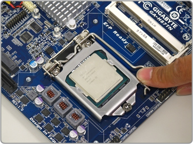
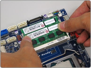
Krok 1 – Instalacja procesora i pamięci
First we need to install the CPU in the motherboard socket as per the standard CPU mounting procedure for all socket 1150 CPUs, paying particular attention to not damage or bend the socket pins. Thin Mini-ITX specifies smaller SO-DIMM DDR3 modules. These simply click into place and are securely held by latches on either side of the module.
|
| |
|
|
|
| |
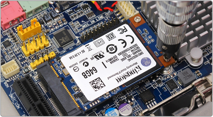
Step 2 – Installing the mSATA SSD
Płyty główne GIGABYTE Thin Mini-ITX obsługują gniazdo mSATA dla łatwej integracji modułu SSD mSATA. Interfejs mSATA SSD zapewnia szybki transfer danych jednocześnie pozwalając na znaczną oszczędność miejsca. Dysk mSATA SSD należy wpiąć w odpowiedni slot a następnie przykręcić za pomocą dwóch niewielkich śrubek. Niektóre obudowy AIO również pozwalają na instalację 2.5” lub 3.5” calowych dysków twardych, dla zwiększenia przestrzeni dyskowej.
|
|
|
|
|
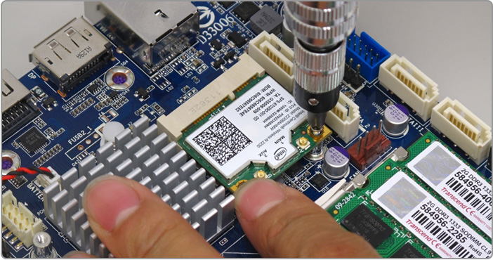
Step 3 – Installing the WiFi/Bluetooth Module
The 3rd step
involves installing the Mini-PCIe WiFi/Bluetooth module. GIGABYTE Thin
Mini-ITX support a half height Mini-PCIe slot which supports a range
of network and communications modules. In similar fashion to the mSATA
slot, the Mini PCIe module sits in the slot held in place by two small
screws.
|
| |
| |
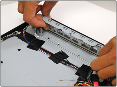
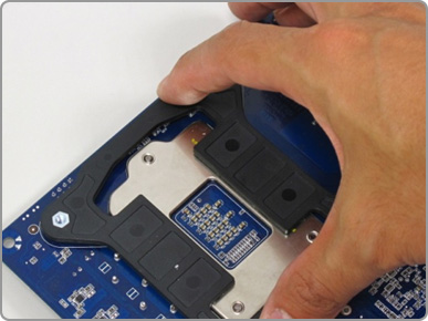
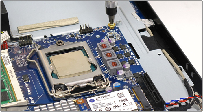
Step 4 – Installing the I/O shell and CPU Cooler Pedestal
Before mounting the
motherboard into the chassis, we need to install the I/O shield and
also the back plate which will hold the integrated CPU cooler securely
in place
|
|
|
|
| |
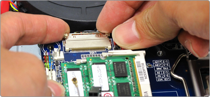
Step 5 – Connecting the LVDS Display and Installing the GIGABYTE Thin Mini-ITX Motherboard
Gdy płyta główna jest już bezpiecznie przytwierdzona do obudowy, możemy się zająć podłączeniem wyświetlacza. Złącze LVDS, standardowe dla płyt Thin Mini-ITX powinno znajdować się wewnątrz obudowy. Tak jak jest to pokazane na poniższym zdjęciu, złącze LVDS należy podłączyć do portu znajdującego się z boku płyty głownej. Upewnij się, że złącze jest właściwie podłączone.
|
|
| |
Nadszedł czas by zainstalować płytę główną GIGABYTE we wnętrzy All-In-One. Zgodnie z zaleceniami, płytę należy przymocować do obudowy za pomocą czterech śrub, na każdym z rogów płyty.
|
|
| |
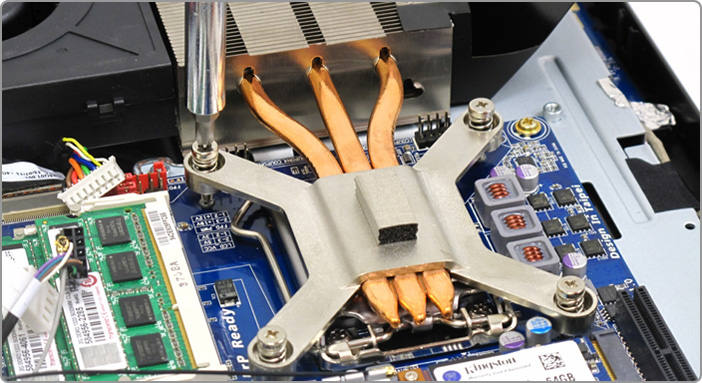
Step 6 – Installing the Heatsink and Cooling Fan
Teraz nadeszła kolej na instalację radiatora sekcji CPU oraz wentylatora. Wygląd wymienionych części może być różny i zależy od modelu obudowy, jednak instalacja przebiega podobnie. W poniższym przykładzie, radiator jest prawidłowo podłączony do płyty nad gniazdem procesora, co zapewnia kontakt pomiędzy CPU a radiatorem, który jest następnie podłączony do wentylatora za pomocą miedziane rurek cieplnych. Wentylator znajduje się na krawędzi obudowy pozwalając by gorące powietrze zostało odprowadzone poza obudowę komputera.
|
|
|
| |
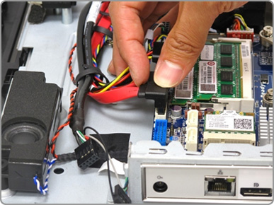
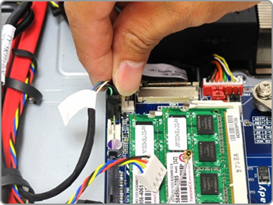
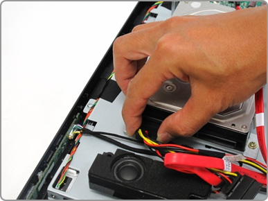
Step 7 – Connecting all the cables
Once the heatsink installation is complete, we can connect all the remaining cables to the motherboard, these include both power and data SATA cables.
|
|
| |
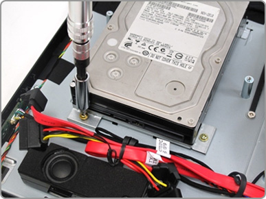
Step 8 – Installing more storage device
Some chassis designs
may also support either 2.5” or 3.5” hard disk drives for additional
data storage. After the motherboard and all cables are installed, you
can install the larger 3.5” hard drive, which is secured in place using
four small screws, then connected to the board using SATA cables.
|
|
|
|
| |
|
|
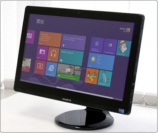
Po kompletnym ukończeniu instalacji wszystkich niezbędnych komponentów, można tylny panel zamocować z powrotem na swoim miejscu. Teraz możesz nareszcie zainstalować system operacyjny - rekomendujemy system Windows 8, wspierający obsługę monitorów dotykowych - i cieszyć się pełną funkcjonalnością Twojego własnego komputera All-In-One!
|
|
| |
|
|
|
|